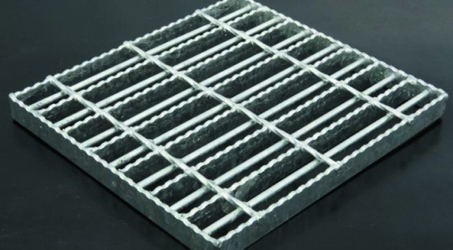
Safety Grating is a variation of safegrid grating designed to prevent a 15mm ball from passing through the gratings. The 6mm twisted transverse bars are usually spaced at 100mm or 50mm centres and a 9mm round bar is welded to the underside to close the gap between the load bearing bars, preventing small objects such as nuts and bolts from passing through the grating.
Safety Grating was originally designed for the offshore industry to satisfy requirements for use in the petroleum activities of the Norwegian sector, however Safety Grating is now used in varying applications where open grid flooring is installed above an existing thoroughfare.
| Petrochemical plants Off shore platforms |
Oil and gas sector |
Particularly suitable to the above applications due to its ability to reduce the chance of tools falling through onto the critical product below.
Mesh Sizes

| Safety Grating | |||
| Load Bearing BarCentres (A) | Transverse BarCentres (B) | Round Bar (9mm) centres (c) | Opening (D) |
| W (41mm) | 50, 100 (mm) | 41mm | 14.5mm (max)* |
| E (33mm) | 50, 100 (mm) | 33mm | 10.5mm (max)* |
| N (30mm) | 50, 100 (mm) | 30mm | 9mm (max)* |
| *Dimensions based on 3mm bearing bars, for 5mm Bars the spacing is reduced by 1mm | |||
Loading Criteria
BS4592-0:2006 gives minimum design loads for platform and walkways as per the below table.
| USE OF PLATFORM OR WALKWAY | UDL | CONCENTRATED LOAD OVER AN AREA OF 300MM x 300MM |
| Light Duty (1 person) | 3.0 kN/m2 | 1.0 kN |
| General (regular two way pedestrian traffic) | 5.0 kN/m2 | 1.0 kN |
| Heavy duty (high density pedestrian traffic) | 7.5 kN/m2 | 1.0 kN |
Lionweld Kennedy have devised a set of load tables to give a quick reference guide to the maximum allowable clear span for each of our grating types. Simply click on the required load table on the side bar on the main Flowforge page to access our loading information.
How to order
- Select the loading requirments from the above table.
- Determine your maximum clear span (open area between supports) and using our load tables select the required load bearing bar size.
- Select the required mesh size.
- Choose your surface type and finish
EXAMPLE
| REQUIRED INFORMATION | FLATBAR SIZE | MESH SIZE | SURFACE TYPE | FINISH |
| EXAMPLE | 25×5 | W 100 (41/100) | Rolled Serrated | Galvanized |
